A good PCB layout for the ACPL-217-56BE involves keeping the input and output circuits separate, using a ground plane, and minimizing the length of the signal traces. It's also recommended to use a 4-layer PCB with a dedicated power plane and a dedicated ground plane.
To ensure reliable operation of the ACPL-217-56BE in high-temperature environments, it's essential to follow proper thermal management practices, such as providing adequate heat sinking, using a thermally conductive material for the PCB, and ensuring good airflow around the device.
Exceeding the maximum rated current of the ACPL-217-56BE can lead to reduced reliability, increased power consumption, and potentially even device failure. It's essential to ensure that the current rating is not exceeded to maintain the device's performance and longevity.
To troubleshoot issues with the ACPL-217-56BE, start by verifying the input voltage and current, checking for any signs of overheating, and ensuring that the device is properly soldered and connected. If the issue persists, consult the datasheet and application notes for guidance or contact Broadcom Limited's technical support.
Yes, the ACPL-217-56BE is a high-frequency device, and as such, it's essential to follow proper EMI/EMC design practices, such as using shielding, filtering, and proper grounding to minimize electromagnetic interference and ensure compliance with relevant regulations.
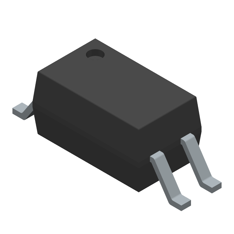 ACPL-217-56BE datasheet
by Avago Technologies
ACPL-217-56BE datasheet
by Avago Technologies