A 4-layer PCB with a solid ground plane and a separate power plane is recommended. The device should be placed near the edge of the board to minimize signal reflections. A 50-ohm microstrip transmission line should be used for the RF signal path.
The device requires a single 3.3V power supply. A 10uF capacitor should be placed between the VCC pin and ground to filter out noise. A 1kohm resistor should be used to bias the VBIAS pin to 1.5V.
The AFBR-5805Z is rated for operation from -40°C to 85°C. However, the device's performance may degrade at temperatures above 70°C. It is recommended to operate the device within the -20°C to 60°C range for optimal performance.
Use a spectrum analyzer to check the RF output signal for distortion or spurious emissions. Verify that the device is properly biased and that the PCB layout is correct. Check for any signs of overheating or physical damage to the device.
Yes, the AFBR-5805Z can be used in a push-pull configuration to improve output power and reduce distortion. However, this requires careful impedance matching and biasing to ensure optimal performance.
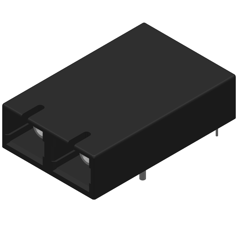 AFBR-5805Z datasheet
by Avago Technologies
AFBR-5805Z datasheet
by Avago Technologies
 Findchips
 Findchips