A good thermal design should be used to minimize thermal resistance. A 2-layer or 4-layer PCB with a solid ground plane and thermal vias is recommended. The device should be placed near a thermal pad or a heat sink to dissipate heat efficiently.
To ensure stability, the output capacitor should be selected carefully. A low-ESR capacitor with a value between 10uF to 22uF is recommended. Additionally, the input capacitor should be placed close to the VIN pin, and the output capacitor should be placed close to the VOUT pin.
The maximum input voltage that can be applied to the AP3418KTR-G1 is 18V. Exceeding this voltage may damage the device.
The output voltage of the AP3418KTR-G1 can be calculated using the following formula: VOUT = 0.8V x (1 + R1/R2), where R1 and R2 are the resistors connected to the FB pin.
The maximum output current that the AP3418KTR-G1 can deliver is 1.5A. Exceeding this current may cause the device to overheat or shut down.
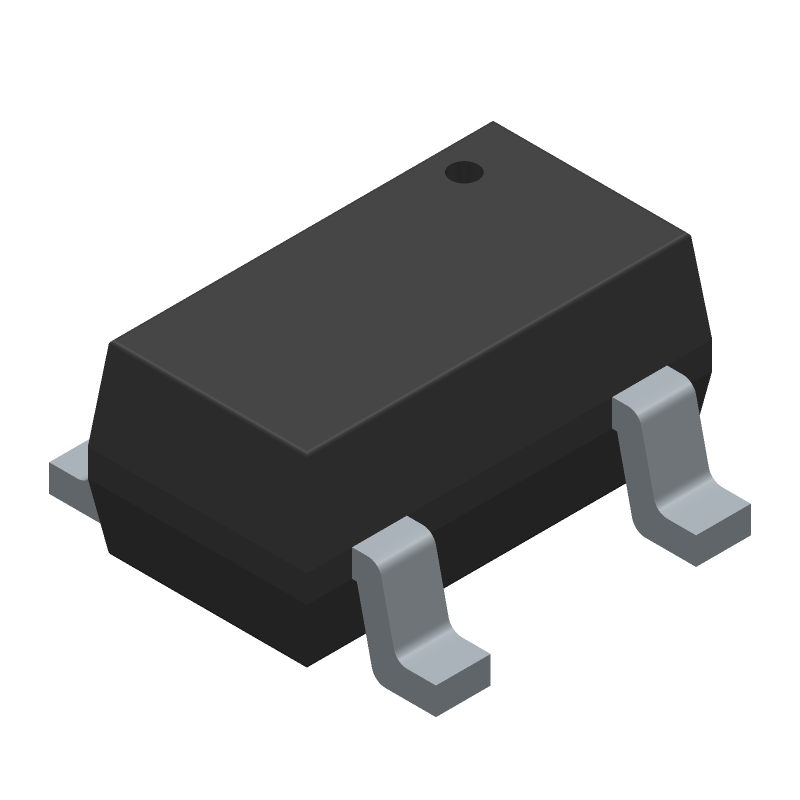 AP3418KTR-G1 datasheet
by Diodes Incorporated
AP3418KTR-G1 datasheet
by Diodes Incorporated