A 4-layer PCB with a solid ground plane and a separate power plane is recommended. The device should be placed near the center of the board, and the antenna should be at least 10mm away from other components.
Implementing a robust error correction mechanism, such as CRC and retransmission, and using a spread spectrum modulation technique can help ensure reliable communication in noisy environments.
The maximum transmission power of the ASSR-1420-302E is +20 dBm. The transmission power can be adjusted by modifying the PA_BIAS voltage and the TX_GAIN register settings.
The ASSR-1420-302E has a built-in low-power mode that can be enabled by setting the PWR_MODE register to 1. Additionally, the device can be put into sleep mode by asserting the nSHDN pin low.
A quarter-wavelength monopole antenna or a chip antenna with a 50-ohm impedance matching network is recommended. The antenna should be designed to operate at the desired frequency band and have a return loss of less than -10 dB.
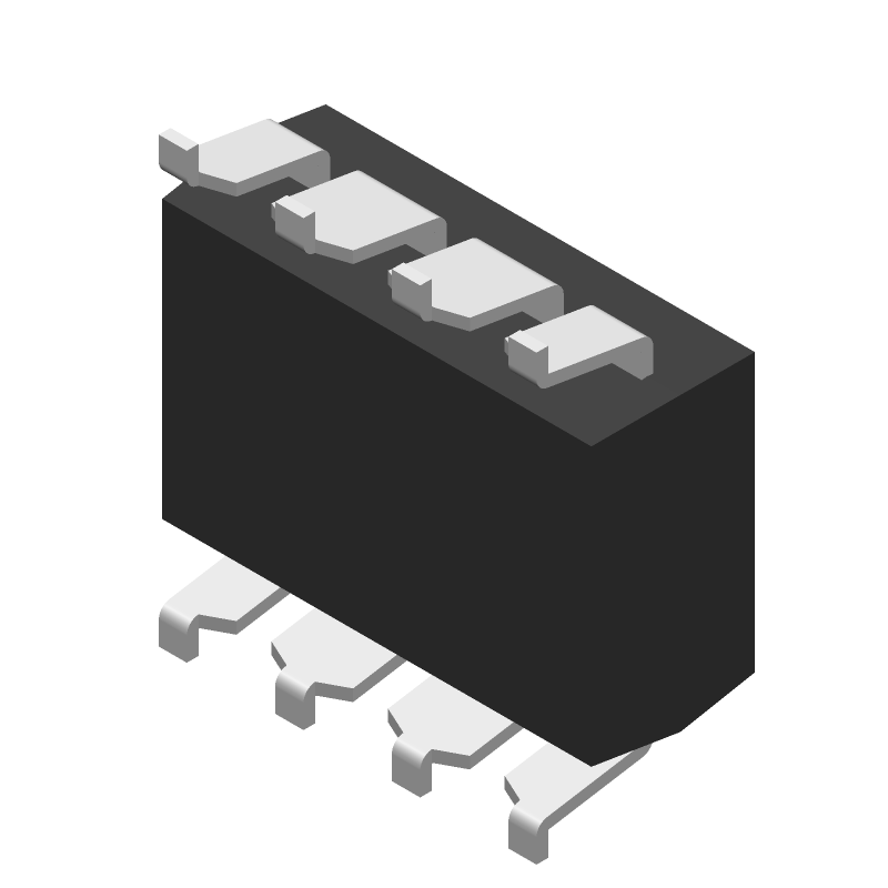 ASSR-1420-302E datasheet
by Avago Technologies
ASSR-1420-302E datasheet
by Avago Technologies