A recommended PCB layout for optimal thermal performance would be to use a 2-layer or 4-layer board with a solid ground plane on the bottom layer, and to place thermal vias under the package to dissipate heat efficiently.
To ensure the device is properly biased, follow the recommended biasing circuit in the datasheet, and make sure to provide a stable voltage supply to the device. Also, ensure that the input and output impedance are matched to minimize signal reflections.
When handling the device, take precautions to prevent electrostatic discharge (ESD) damage by using an ESD wrist strap or mat, and avoid touching the pins or exposed die. Also, handle the device by the body or pins, not the leads, to prevent bending or damage.
To troubleshoot issues with the device, start by checking the power supply voltage and ensuring it is within the recommended range. Then, verify that the input and output impedance are matched, and check for any signs of oscillation or instability. Use a spectrum analyzer or oscilloscope to visualize the signal and identify any issues.
When using the BCM846BS-7, be aware of the thermal considerations such as the maximum junction temperature (Tj) of 150°C, and ensure that the device is properly heat-sinked to prevent overheating. Also, consider the thermal resistance (Rth) of the package and the PCB to ensure efficient heat dissipation.
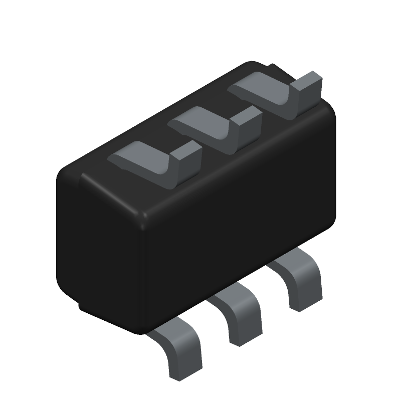 BCM846BS-7 datasheet
by Diodes Incorporated
BCM846BS-7 datasheet
by Diodes Incorporated


