A good PCB layout for the GBU1010 involves keeping the input and output traces short and away from each other, using a solid ground plane, and placing the input and output capacitors close to the device. Additionally, using a shielded inductor and placing it away from the device can help reduce EMI.
To ensure stability, make sure the input and output capacitors are properly selected and placed close to the device. Also, ensure the inductor is properly selected and the PCB layout is optimized for minimal parasitic inductance and capacitance. Additionally, a soft-start circuit can be used to reduce inrush current and prevent oscillation.
The maximum ambient temperature range for the GBU1010 is -40°C to +125°C. However, the device's performance and reliability may degrade at extreme temperatures, so it's recommended to operate the device within a temperature range of -20°C to +85°C for optimal performance.
Yes, the GBU1010 is suitable for high-reliability applications. It's built with a robust design and has undergone rigorous testing to ensure its reliability. However, it's essential to follow proper design and manufacturing guidelines to ensure the device operates within its specified parameters.
To troubleshoot issues with the GBU1010, start by checking the input and output voltages, currents, and waveforms using an oscilloscope. Verify that the device is properly powered and that the input and output capacitors are properly selected and placed. Check for any signs of overheating, and ensure the PCB layout is optimized for minimal parasitic inductance and capacitance.
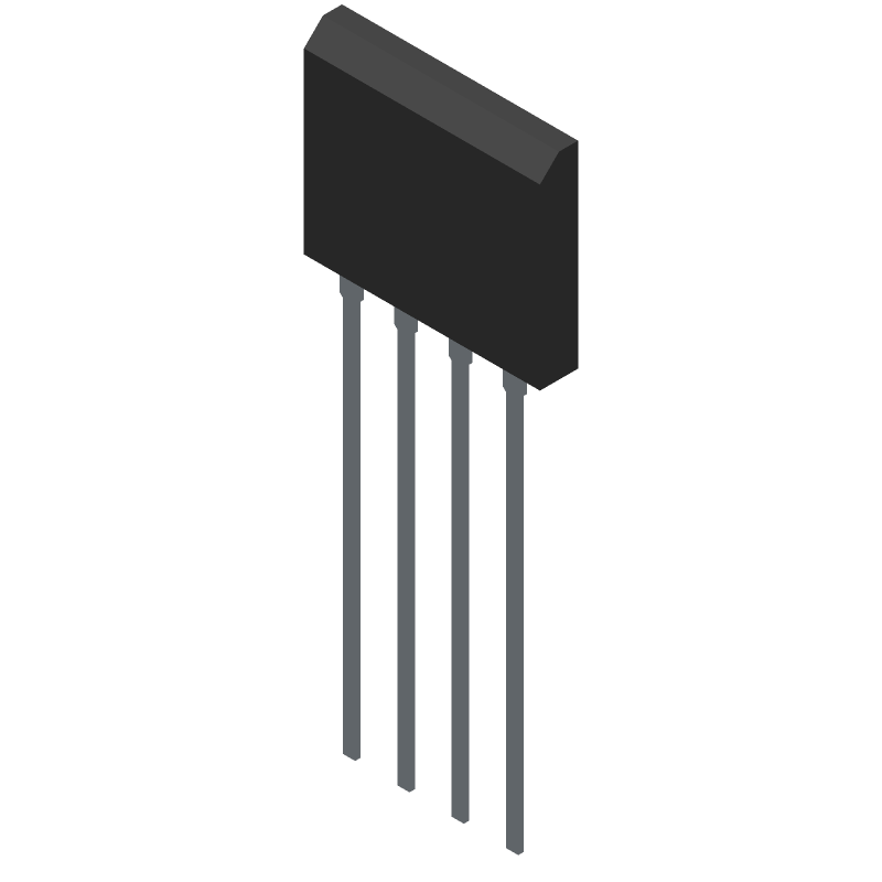 GBU1010 datasheet
by Diodes Incorporated
GBU1010 datasheet
by Diodes Incorporated
