A good PCB layout for HCPL-2531 involves keeping the input and output circuits separate, using a ground plane, and minimizing the length of the input and output traces. It's also recommended to use a shielded cable for the input signal and to keep the cable away from noise sources.
To ensure reliability in high-temperature applications, it's essential to follow proper thermal management practices, such as providing adequate heat sinking, using a thermally conductive material for the PCB, and keeping the device away from heat sources. Additionally, ensure that the device is operated within its recommended temperature range.
Common failure modes of HCPL-2531 include overvoltage, overcurrent, and excessive temperature. To mitigate these, ensure that the device is operated within its recommended voltage and current ratings, and provide adequate heat sinking and thermal management. Additionally, use protective circuits such as voltage regulators and current limiters to prevent overvoltage and overcurrent conditions.
To troubleshoot issues with HCPL-2531, start by verifying the input signal and power supply voltage. Check for proper PCB layout and thermal management. Use an oscilloscope to measure the input and output signals, and verify that the output logic levels are correct. If issues persist, consult the datasheet and application notes for guidance.
Yes, the HCPL-2531 can be used in high-speed applications. However, it's essential to consider the device's bandwidth and rise time, as well as the PCB layout and signal integrity. Ensure that the input signal is properly terminated, and use a low-jitter clock source to minimize signal distortion.
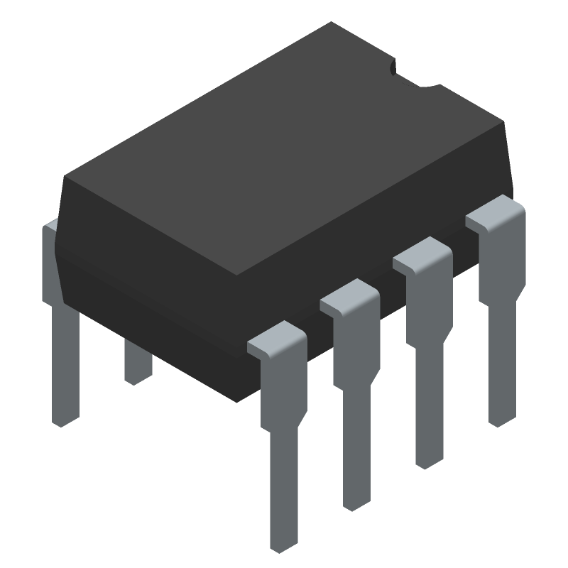 HCPL-2531 datasheet
by Avago Technologies
HCPL-2531 datasheet
by Avago Technologies