A good PCB layout for HCPL-4200-000E involves keeping the input and output traces separate, using a ground plane, and minimizing the length of the input traces. It's also recommended to use a 0.1uF capacitor between VCC and GND pins to filter out noise.
To ensure reliable operation of HCPL-4200-000E in high-temperature environments, it's essential to follow proper thermal management practices, such as providing adequate heat sinking, using a thermally conductive material, and keeping the device within its recommended operating temperature range.
The recommended input signal amplitude for HCPL-4200-000E is typically between 10mV to 1V, and the frequency range is up to 10MHz. However, the optimal input signal amplitude and frequency may vary depending on the specific application and noise environment.
To troubleshoot common issues with HCPL-4200-000E, check the input signal amplitude and frequency, ensure proper power supply decoupling, and verify that the device is operated within its recommended specifications. Also, check for any noise or interference in the system that may be affecting the device's performance.
Yes, HCPL-4200-000E is suitable for use in high-reliability or safety-critical applications, such as in industrial control systems, medical devices, or aerospace applications, due to its high isolation voltage, low propagation delay, and high common-mode rejection ratio.
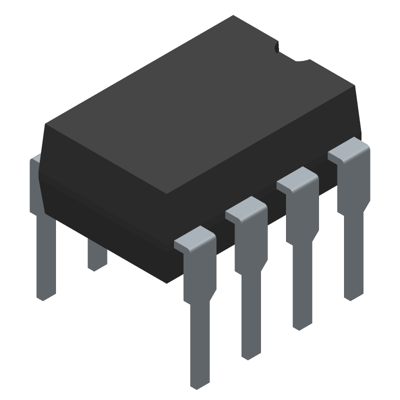 HCPL-4200-000E datasheet
by Avago Technologies
HCPL-4200-000E datasheet
by Avago Technologies