Texas Instruments recommends a 4-layer PCB with a solid ground plane and a separate analog ground plane to minimize noise and thermal gradients. The LM45CIM3 should be placed near the thermal source, and the thermal pad should be connected to a large copper area to dissipate heat.
The LM45CIM3 has an internal calibration trim, but it may require additional calibration for high-accuracy applications. Texas Instruments recommends using a precision temperature source, such as a thermocouple or RTD, to calibrate the LM45CIM3. The calibration process involves measuring the output voltage at multiple temperatures and adjusting the trim to achieve the desired accuracy.
The maximum cable length for the LM45CIM3's output signal depends on the specific application and the noise environment. As a general rule, Texas Instruments recommends keeping the cable length as short as possible (less than 10 inches) and using a shielded cable to minimize noise pickup. Additionally, the output signal should be terminated with a 1 kΩ to 10 kΩ resistor to prevent signal reflections.
The LM45CIM3 is designed to operate in a variety of environments, including those with high vibration or shock. However, Texas Instruments recommends following proper PCB design and assembly practices to ensure the device is securely attached to the board and that the thermal pad is properly connected to a heat sink. Additionally, the device should be tested and validated in the specific application environment to ensure reliable operation.
To ensure EMC with the LM45CIM3, Texas Instruments recommends following proper PCB design and layout practices, such as separating analog and digital circuits, using a solid ground plane, and minimizing loop areas. Additionally, the device should be shielded from external electromagnetic interference (EMI) sources, and the output signal should be filtered or shielded to prevent EMI radiation.
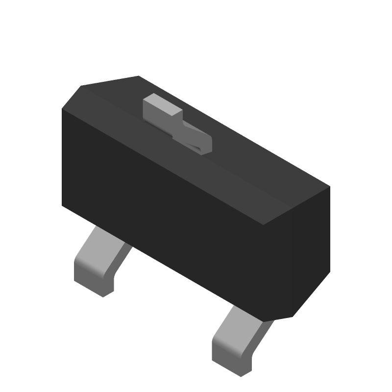 LM45CIM3 datasheet
by Texas Instruments
LM45CIM3 datasheet
by Texas Instruments