-
A 2-layer or 4-layer PCB with a solid ground plane and a separate layer for the high-frequency signals is recommended. Keep the input and output capacitors close to the IC, and use short, wide traces for the high-current paths.
-
Monitor the input voltage, output current, and junction temperature to ensure they are within the specified limits. Use a thermal management system, such as a heat sink, to keep the junction temperature below 125°C.
-
A low-ESR, X7R or X5R ceramic capacitor with a value of 10-22 μF is recommended. The capacitor should be placed close to the VIN pin and have a voltage rating of at least 25 V.
-
Use a shielded transformer, keep the input and output cables short and away from each other, and add EMI filters or common-mode chokes to the input and output lines. Also, ensure good PCB layout practices, such as separating high-frequency signals from low-frequency signals.
-
The maximum output current capability of LQA10T300 is 3 A. However, the actual output current capability may be limited by the thermal design and the input voltage.
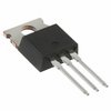
 LQA10T300 datasheet
by Power Integrations
