The recommended PCB layout involves keeping the device away from high-current carrying traces, using a solid ground plane, and placing thermal vias under the device. For thermal management, a heat sink or thermal pad is recommended to keep the junction temperature below 125°C.
To ensure EMC and reduce EMI, use a shielded enclosure, keep the device away from antennas and high-frequency circuits, and use filtering and shielding on the input/output lines. Additionally, follow good PCB design practices, such as using a solid ground plane and minimizing loop areas.
The recommended power sequencing involves applying the power supplies in the following order: VCC, AVCC, and DVCC. The voltage ramp-up procedure should be slow and controlled, with a rate of 1-2 ms/V to prevent latch-up and ensure reliable operation.
To troubleshoot and debug issues, use a combination of visual inspection, signal probing, and logic analysis. Check for proper power supply, clock signal integrity, and signal routing. Use Broadcom's recommended evaluation boards and development tools to simplify the debugging process.
The MGA-61563-TR1G meets industry standards for reliability and quality, including AEC-Q100 and ISO/TS 16949. The device undergoes rigorous testing and inspection, including environmental stress screening, to ensure high reliability and quality.
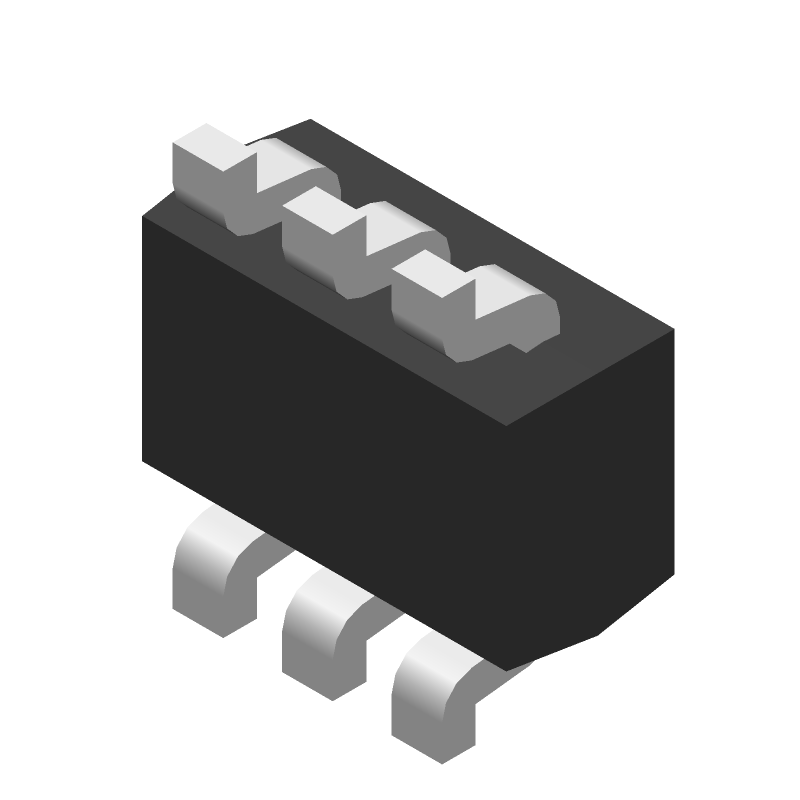 MGA-61563-TR1G datasheet
by Avago Technologies
MGA-61563-TR1G datasheet
by Avago Technologies