-
A 2-layer or 4-layer PCB with a solid ground plane and thermal vias under the IC is recommended. Keep the input and output capacitors close to the IC and use short, wide traces for the power paths.
-
Ensure that the output capacitor has a low ESR and is placed close to the IC. Also, add a 10nF-100nF ceramic capacitor in parallel with the output capacitor to improve stability.
-
The maximum input voltage is 26V, but it's recommended to keep it below 24V to ensure reliable operation and prevent damage to the IC.
-
No, a ceramic capacitor is not recommended for CIN due to its high ESR. Use a low-ESR electrolytic capacitor or a polymer capacitor instead.
-
The output voltage can be adjusted by changing the resistor divider ratio (R1 and R2) connected to the FB pin. Use the formula in the datasheet to calculate the required resistor values.
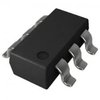
 MP2000DJ-ADJ-LF-Z datasheet
by Monolithic Power Systems