-
A good PCB layout is crucial for the MP8101DJ-LF-Z. Ensure that the input and output capacitors are placed close to the IC, and the high-current paths are short and wide. Use a solid ground plane and avoid routing high-frequency signals under the IC. Refer to the application note AN-114 for more detailed guidelines.
-
Choose input capacitors with low ESR (Equivalent Series Resistance) and high ripple current rating. For output capacitors, select ones with low ESR, high capacitance, and a voltage rating that meets or exceeds the output voltage. The datasheet recommends X5R or X7R ceramic capacitors with a minimum capacitance of 10uF for both input and output.
-
The MP8101DJ-LF-Z is rated for operation up to 85°C ambient temperature. However, for reliable long-term operation, it's recommended to keep the ambient temperature below 70°C to ensure the junction temperature remains within the specified range.
-
To ensure stability, follow the recommended component values and PCB layout guidelines. Additionally, make sure the input and output capacitors are properly decoupled, and the feedback network is correctly configured. If oscillations occur, try adding a small capacitor (e.g., 10nF) in parallel with the feedback resistor.
-
The MP8101DJ-LF-Z has a built-in undervoltage lockout (UVLO) circuit that prevents startup until the input voltage reaches approximately 2.5V. This ensures that the device starts up reliably and prevents damage from low input voltages.
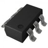
 MP8101DJ-LF-Z datasheet
by Monolithic Power Systems