TE Connectivity provides a recommended PCB layout and land pattern in their application note AN-1043, which can be found on their website. It's essential to follow this layout to ensure proper thermal performance and to prevent overheating.
To ensure reliability in high-vibration environments, it's crucial to follow proper mounting and soldering techniques. TE Connectivity recommends using a strain relief mechanism to secure the component to the PCB, and to use a solder alloy with a high fatigue resistance. Additionally, conformal coating can help to protect the component from environmental stresses.
The maximum allowable power derating for MPT100A6R8F depends on the ambient temperature and the airflow around the component. As a general rule, TE Connectivity recommends derating the power by 1% for every 1°C above 25°C. However, it's essential to consult the datasheet and to perform thermal simulations to determine the maximum allowable power derating for a specific application.
While MPT100A6R8F is rated for operation up to 150°C, TE Connectivity does not recommend using it in environments above 150°C. Prolonged exposure to high temperatures can cause degradation of the component's performance and reliability. If your application requires operation above 150°C, it's recommended to consult with TE Connectivity's technical support team to discuss alternative solutions.
To troubleshoot thermal issues with MPT100A6R8F, start by verifying that the component is properly mounted and soldered to the PCB. Check for any signs of overheating, such as discoloration or deformation of the component. Use thermal imaging or temperature measurement tools to identify hotspots and to determine the temperature of the component. Consult the datasheet and application notes for guidance on thermal management and to determine the root cause of the thermal issue.
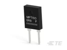 MPT100A6R8F datasheet
by TE Connectivity
MPT100A6R8F datasheet
by TE Connectivity