Texas Instruments provides a recommended PCB layout in the application note 'AN-1149 PCB Layout Guidelines for TI Logic Devices'. Following these guidelines can help minimize signal integrity issues and ensure optimal performance.
The SN74ACT3651-15PCB has a maximum junction temperature of 150°C. To manage thermal issues, ensure good airflow, use a heat sink if necessary, and follow the thermal management guidelines in the datasheet. You can also use thermal simulation tools to estimate the device's temperature under different operating conditions.
The SN74ACT3651-15PCB is a 3-state bus transceiver, and the recommended input termination depends on the application. For high-speed signals, use a series terminator (e.g., 22-33 ohms) to minimize reflections. For low-speed signals, a parallel terminator (e.g., 1 kohm to 10 kohm) can be used. Consult the datasheet and application notes for more information.
The SN74ACT3651-15PCB is a 3.3V device, but it is 5V tolerant on the input pins. However, the output voltage will still be 3.3V. If you need to interface with a 5V system, you may need to use level translators or voltage dividers to ensure signal integrity.
To ensure signal integrity, follow the guidelines in the datasheet and application notes. Use controlled impedance traces, minimize trace lengths, and avoid vias and stubs. Also, use signal termination, and consider using signal conditioning components (e.g., series resistors, capacitors) to filter out noise and reflections.
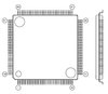 SN74ACT3651-15PCB datasheet
by Texas Instruments
SN74ACT3651-15PCB datasheet
by Texas Instruments
 Findchips
 Findchips