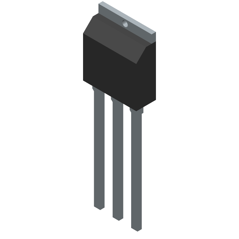
-
The maximum safe operating area (SOA) for the STU5N60M2 is not explicitly stated in the datasheet, but it can be estimated based on the device's thermal and electrical characteristics. A safe operating area can be defined as the region where the device can operate without exceeding its maximum ratings. For the STU5N60M2, this region is typically bounded by the maximum drain-source voltage (Vds), maximum drain current (Id), and maximum junction temperature (Tj). Engineers can use simulation tools or consult with STMicroelectronics' application notes to determine the SOA for their specific application.
-
To ensure the STU5N60M2 is properly biased for optimal performance, engineers should follow the recommended biasing conditions outlined in the datasheet. This includes setting the gate-source voltage (Vgs) within the recommended range, typically between 2V and 5V, and ensuring the drain-source voltage (Vds) is within the maximum rating. Additionally, engineers should consider the device's threshold voltage (Vth) and ensure the gate-source voltage is sufficient to fully turn on the device. Proper biasing is critical to achieve the desired performance, including low on-state resistance and high switching speeds.
-
Thermal management is critical for the STU5N60M2, as excessive junction temperature (Tj) can lead to reduced performance, reliability, and lifespan. Engineers should consider the device's thermal resistance (Rthja) and ensure adequate heat sinking, such as using a heat sink or thermal interface material, to keep the junction temperature within the recommended range. Additionally, engineers should consider the device's power dissipation (Pd) and ensure it is within the maximum rating. Proper thermal management is essential to achieve reliable operation and prevent thermal runaway.
-
Electrostatic discharge (ESD) can damage the STU5N60M2, so engineers should take precautions to prevent ESD events. This includes handling the device with anti-static wrist straps, mats, or bags, and ensuring the device is properly grounded during assembly and testing. Additionally, engineers can use ESD protection devices, such as TVS diodes or ESD protection arrays, to protect the device from ESD events. Proper ESD protection is essential to prevent damage and ensure reliable operation.
-
Proper PCB layout is critical for the STU5N60M2 to ensure reliable operation and minimize parasitic effects. Engineers should consider the device's pinout and ensure proper routing of the drain, source, and gate pins. This includes minimizing the length and inductance of the drain and source traces, and ensuring the gate trace is properly terminated to prevent ringing. Additionally, engineers should consider the device's thermal management and ensure adequate heat sinking and thermal dissipation. Proper PCB layout is essential to achieve optimal performance and reliability.
 STU5N60M2 datasheet
by STMicroelectronics
Findchips
 STU5N60M2 datasheet
by STMicroelectronics
 Findchips