A good PCB layout for the TPS826711SIPT involves placing the input and output capacitors close to the device, using a solid ground plane, and minimizing the length of the input and output traces. A 4-layer PCB with a dedicated power plane and a solid ground plane is recommended.
To ensure stability, it's essential to follow the recommended capacitor values and types, and to place them close to the device. Additionally, the output voltage can be stabilized by adding a small ceramic capacitor (e.g., 10nF) in parallel with the output capacitor.
The TPS826711SIPT can handle input voltages up to 17V, but it's recommended to operate within the specified input voltage range (5.5V to 15V) for optimal performance and reliability.
The TPS826711SIPT is rated for operation up to 125°C, but it's essential to consider the device's power dissipation and thermal management when operating in high-temperature environments. A heat sink or thermal pad may be necessary to ensure reliable operation.
To troubleshoot output voltage issues, check the input voltage, output capacitor values, and PCB layout. Verify that the device is properly soldered and that there are no shorts or opens on the PCB. Use an oscilloscope to measure the output voltage and check for any oscillations or noise.
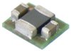 TPS826711SIPT datasheet
by Texas Instruments
TPS826711SIPT datasheet
by Texas Instruments