-
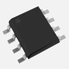
A good PCB layout for the TSM1011IDT involves keeping the input and output traces short and separate, using a solid ground plane, and placing decoupling capacitors close to the device. A 4-layer PCB with a dedicated power plane and a dedicated ground plane is recommended.
-
The TSM1011IDT requires a single 3.3V power supply. It's recommended to power the device with a clean and stable voltage source. The power sequencing requirement is to power up the device after the input voltage has reached 2.7V to ensure proper operation.
-
The recommended input capacitance is 10nF to 100nF, and the recommended output capacitance is 10uF to 100uF. The actual capacitance values may vary depending on the specific application and requirements.
-
The TSM1011IDT has a thermal pad on the bottom of the package. It's recommended to connect this pad to a solid ground plane on the PCB to dissipate heat. Additionally, ensure good airflow around the device and consider using a heat sink if the device is expected to operate at high temperatures.
-
The TSM1011IDT has built-in ESD protection, but it's still recommended to follow proper ESD handling procedures when handling the device. Use an ESD wrist strap or mat, and ensure the PCB is properly grounded to prevent static damage.
 TSM1011IDT datasheet
by STMicroelectronics
Findchips
